
If you would like to learn more about the IAEA’s work, sign up for our weekly updates containing our most important news, multimedia and more.
Equipment
Nuclear Medicine
On this page
- Dose calibrator
- Gamma camera
- SPECT
- PET
- Dedicated cardiac SPECT systems
- Hybrid imaging
- Intra–operative probes
- Handheld gamma cameras
- Quality assurance – dose calibrator
- Quality assurance – gamma cameras
- Quality assurance – SPECT
- Quality assurance – PET
- Quality assurance – software
- Image reconstruction
Dose calibrator
The calibrated re-entrant ionization chamber, commonly known as a radionuclide calibrator or dose calibrator, is the most used instrument in nuclear medicine to measure radioactivity. Commercial systems include a cylindrical well ionization chamber connected to a microprocessor-controlled electrometer providing calibrated measurements for a range of common radionuclides.
Important principles
The chamber is usually constructed of aluminium walled cavity filled with argon under pressure. A well liner, made of low atomic number material which can be removed for cleaning, prevents the ionization chamber from becoming accidentally contaminated. A sample holder is provided into which a vial or syringe can be placed to ensure that it is positioned optimally within the chamber. The chamber is typically shielded by the manufacturer with 6 mm of lead to ensure low background readings. Depending on the location of the dose calibrator, the user may require additional shielding, either to reduce background in the chamber or to protect the operator when measuring radionuclides of high energy and activity. If additional shielding is used, the dose calibrator should be recalibrated, or correction factors determined to ensure the accuracy of the activity readings.
A dose calibrator can be calibrated in terms of activity using an appropriate activity standard that is directly traceable to the international system of measurements (SI). Using the activity standard, a calibration factor for the ionization chamber can be determined for the specific radionuclide.
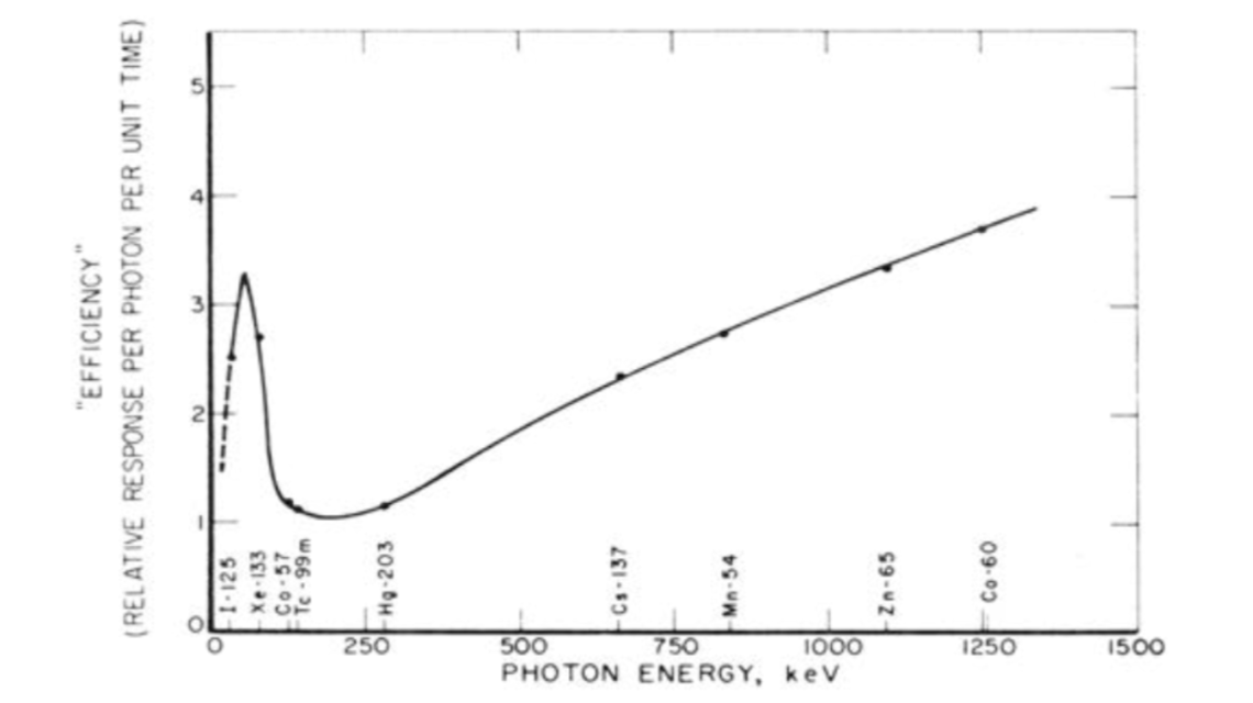
Efficiency curve as a function of photon energy (Source: IAEA Nuclear Medicine Physics)
The IAEA reference book Nuclear Medicine Physics gives a comprehensive overview to the field of nuclear medicine physics and also provides specific information and guidelines to radiation protection and commonly used equipment.
Gamma camera
Imaging forms an important part in the field of nuclear medicine and a number of different imaging devices have been developed. One well established and broadly used imaging technique is the single photon emission computed tomography (SPECT) which was established in the early 1960s. Systems emerged in the 1970s that incorporated the Anger gamma camera which provided the basis for the modern day systems. Little changed from these original systems until in the 1990s when the imaging techniques of SPECT and computed tomography (CT) were combined to form a hybrid SPECT/CT scanner as it is mostly used today.
Important Principles
Gamma camera systems are comprised of four basic elements: the collimator, which defines the lines of response (LORs), the radiation detector, which counts incident γ-photons, the computer system, which uses data from the detector to create 2‑D histogram images of the number of counted photons and the gantry system, which supports and moves the gamma camera and patient.
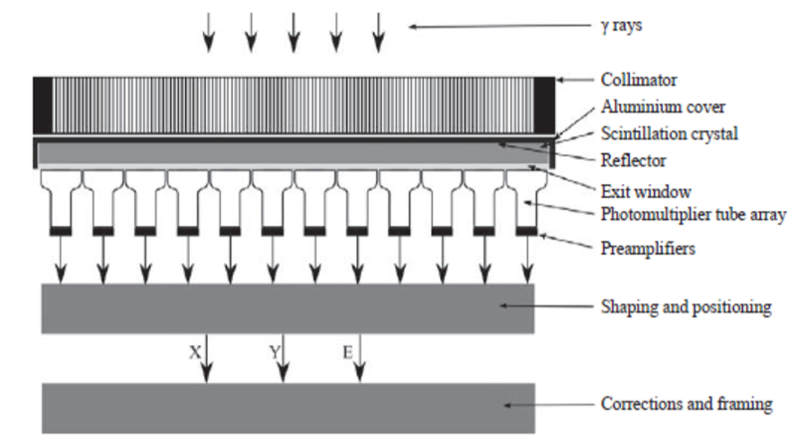
Schematic diagram showing the major components of a gamma camera (Source: Nuclear Medicine Physics, p.313)
Forming an image with a gamma camera means establishing a relationship between points on the image plane and positions in the object. This is sometimes referred to as LOR (lines of response): ideally, each position in the image provides information about the activity on a unique line through the object.
The collimator functions as a mechanical lens as it prevents photons emitted along directions that do not lie along the LOR from reaching the detector. The scintillation crystal in the gamma camera converts γ-ray photons incident on the crystal into a number of visible light photons. The next element in the radiation detector is the photodetector array. This array measures the distribution of scintillation photons incident on the array and converts it into a set of pulses whose charge is proportional to the number of scintillation photons incident on each corresponding element in the array. In clinical gamma cameras, the
photodetector array is comprised of a set of 30–90 PMTs (photomultiplier tubes) arranged in a hexagonal close packed arrangement. In some commercial designs, PMTs have been replaced by semiconductor detectors such as photodiodes. To make subsequent analysis of the pulse easier and more resistant to electrical noise, the pulse is amplified and shaped prior to processing to estimate the interaction position and photon energy.
Typically, SPECT systems use a gamma camera detector capable of rotating around the object of interest in order to create projection images at multiple angles to provide the information necessary to reconstruct a three-dimensional distribution of activity. SPECT data are usually acquired with dual head detector-systems over 360° where the two heads are typically orientated in an opposing fashion (H-mode) and the sampling is achieved by 180° rotation of each head. In contrast it is also possible that the two heads are orientated at 90° to each other (L-mode) with rotation of the detectors through 90°. Therefore only 180°- data are acquired but the distance between the object of interest and the detector can be minimized which is a big advantage in cardiac applications for example.
The properties and principles of operation of SPECT can be found in IAEA Human Health Series No.36 “SPECT/CT Atlas of Quality Control and Image Artefacts”. Additional information is provided in the reference book Nuclear Medicine Physics (IAEA). These books provide guidance for specifications and operation of different imaging devices as well as general information to the topic of nuclear medicine.
SPECT
Single Photon Emission Computed Tomography (SPECT) is used for imaging organ function, and in oncology, for detection of a specific types of tumors. SPECT images provide specific pathological uptake information, however it is sometimes difficult to determine the position of the uptake with respect to the patient anatomy. The use of co-registered SPECT and CT images provides a tool to overcome this ambiguity, and thus increase the diagnostic accuracy of the examinations. Another important application of the CT is its use to make a relatively reliable attenuation correction of the SPECT-study, an attribute that is significant in nuclear cardiology.
Important principles
CT equipment can have capabilities to acquire lower dose images to be used for anatomical localization and attenuation correction, as well as higher resolution images to be used for diagnostic applications. If using (higher dose) diagnostic CT imaging, additional structural shielding may be required in accordance with national regulations. SPECT/CT equipment is usually placed in a nuclear medicine department which means that the NM-staff must be fully trained to run both the SPECT and the CT machines, including training in radiation protection issues. Cooperation of the NM department with a radiological department is necessary. If diagnostic CT-studies are acquired with SPECT images they should be analyzed by a qualified radiologist together with a nuclear medicine specialist. All imaging and diagnostic assessment should be made following recommendations from professional organizations. A quality control programme should be in place and should include not only the individual types of equipment but also parameters important for the combined image registration.
The IAEA has published a document regarding the clinical use of SPECT/CT, which include a section on training. Structural shielding of a CT-installation is discussed on the IAEA website Radiation Protection of the Patient. The basic physics of SPECT/CT is presented in the IAEA Handbook of Nuclear Medicine Physics. The reference to AAPM CRCPD Annual Meeting contains several relevant lectures that were recorded live. For a detailed description of SPECT and CT separately, as well as quality control issues, the reader is referred to other sections of this website.
PET
The use of PET/CT has been growing exponentially, and in all regions of the world. This great success is based on the ability of the equipment to combine anatomical and functional information in one patient examination, which optimizes the clinical utility of the images. The success is also based on the introduction of FDG labeled with F-18, a radionuclide with a half-life long enough to allow for transportation between the site of production and the user. The clinical application of FDG includes cardiology and neurology but mainly oncology where it is used for diagnosing, staging and re-stating of cancer, as well as in the planning and monitoring of cancer treatment.
Important principles
Establishment of a successful PET/CT practice requires integration of the two techniques on several levels, including planning and design of the PET/CT facility, staffing (categories, number, training), supply of radiopharmaceuticals, patient preparation and management procedures, imaging protocols, radiation protection and quality assurance. It is important that a medical physicist actively take part in the planning of the facility as well as in the routine work such as the quality control programme.
The IAEA has recently published a document entitled Quality Assurance for PET and PET/CT Systems, which outlines QC procedures for PET/CT provides guidance about the specifications and prerequisites required for acceptance testing of PET and PET/CT scanners, including the professionals to be involved, definitions of applications, minimal required configurations and corresponding performance parameters, as well as ancillary equipment. The PET acceptance tests described in this publication adhere closely to the NEMA 2007 standard. It also provides guidelines for routine QC of PET and PET/CT scanners, as well as a framework for setting reference values, tolerance values and action levels.
The establishment of a PET/CT facility is discussed in the article by Shreve. More extended information is found in the IAEA document Planning a Clinical PET Centre. The basic physics and technology of PET/CT is provided in the article by Townsend and the IAEA publication on Quality Assurance for PET and PET/CT Systems, as well as in a powerpoint-presentation on the IAEA Radiation Protection of the Patient website, which also covers radiation protection matters. Structural shielding of a PET/CT facility is discussed in the document from AAPM Task Group 108.
Dedicated cardiac SPECT systems
New semi-erect or upright imaging cameras can decrease the problems of extra-cardiac activity contaminating cardiac imaging (hepatic, gastrointestinal uptake). Semiconductor detectors with much higher sensitivity as compared with conventional detectors allow for lower doses of radiopharmaceuticals, a reduction in imaging time, or a combination of both. This has the potential to reduce cost and lower radiation to the patient. Furthermore, the incorporation of these new detectors into novel camera designs provides outstanding spatial resolution and contrast. Some cameras using these detectors permit optimal proximity from the chest wall thus further increasing image resolution. These cameras also exhibit improved energy resolution for better dual isotope imaging. The reduced weight and size of the detectors compared to conventional cameras allow mobility throughout the department, even under emergency conditions in coronary care or intensive care units. Some gantry designs will also allow coupling with CT machines providing the possibility of attenuation correction, calcium scoring, and simultaneous assessment of coronary anatomy. These cameras are not general-purpose instruments, but rather are intended to be used for cardiology studies only, so with the cost still quite significant, the purchase of such equipment would only be justified for a laboratory with very high cardiac workload or a large university department. Physiological cardiac imaging has been the mainstay of imaging for at least 30 years. Renewed and significant investment in research and development in nuclear cardiology is required to allow the field to meet its full potential as an essential diagnostic tool in the care of cardiac patients. Such investment is best directed globally, enabling talented physicians and scientists to focus on improving the field(Nuclear Cardiology: Its Role in Cost Effective Care).
Hybrid imaging
The term hybrid imaging refers to the combination of two or more imaging methods in order to combine their benefits in a new technique. Two important examples are PET/CT, as a combination of positron emission tomography (PET) and computed tomography (CT), and SPECT/CT as a combination of single photon emission computed tomography (SPECT) and computed tomography (CT).
Important principles
Many radiopharmaceuticals that are used in oncology are specific for tumour physiology and therefore the tracers provide limited anatomical information. As a result, localization of metastatic or nodal disease is difficult. Therefore PET/SPECT are combined with CT to provide useful and complementary clinical information: PET/SPECT can identify functional abnormalities that might be undetectable on CT alone. CT is normally only able to identify malignancies after structural changes have occurred, however the images provide detailed anatomical information.. Software tools allow the display of the PET or SPECT and CT images, either side by side, or as fused images in which the PET or SPECT images are superimposed on the CT images. An example of the benefits of functional mapping is shown in the figure below. In this 123I-metaiodobenzylguanidine (mIBG) study, the SPECT images suggest that the uptake is in the liver, but it is not completely clear which areas of the liver actually show this uptake. Once fused with the CT images it is possible to determine the regions of the affected liver tissue, but this can be done with great anatomical accuracy on the CT image.
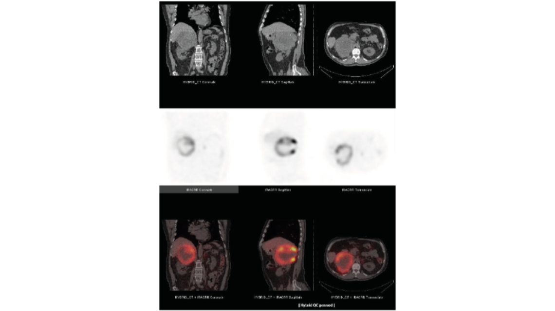
123I-mIBG SPECT/CT study of the lower thorax/upper abdomen (Source: IAEA Human Health Series No.36, p.17)
The properties and principles of operation of the PET can be found in the technical reference book IAEA Human Health Series No.1 “Quality Assurance for PET and PET/CT Systems” and for the SPECT in IAEA Human Health Series No.36 “SPECT/CT Atlas of Quality Control and Image Artefacts”. These books provide guidance for specifications and operation of the imaging devices as well as guidelines for the routine quality control of the equipment. In addition, the IAEA reference book Nuclear Medicine Physics gives a comprehensive overview to the field of nuclear medicine physics in general.
Intra–operative probes
Non-imaging radiation detection is an essential component of nuclear medicine with various detection and measurement devices available. Intra-operative probes, small hand-held counting devices, are widely used in the management of cancer. They help identify and localize sentinel lymph nodes, thereby reduce the need for more extensive surgery. These detectors can also be used to identify and localize visually occult disease during surgery following systemic administration of a radiolabelled antibody or other tumour-avid radiotracer.
Important Principles
Intra-operative probes have been used almost exclusively for counting X-rays and gamma rays, although these detectors can also be utilized for the detection of beta radiation (electrons and positrons). Intra operative gamma probes are available with either scintillation or semiconductor ionisation detectors. Scintillation-based detector probes have the advantage of relatively low cost and high sensitivity, especially for medium to high energy photons. However, scintillation detectors are bulky and have poor energy resolution relative to semiconductor-based probes. Semiconductor based probes are compact and have excellent energy resolution, but, on the other hand, are very thin and therefore have a lower intrinsic sensitivity than scintillation-based detectors, especially for medium to high energy X-rays and gamma rays.
Quality control tests of intra-operative probes should include a daily bias check for both the primary and any backup battery to verify that the bias voltage is within the acceptable range. As intra-operative probes may not provide a display of the energy spectrum, it may not be possible to visually check that the probe is properly peaked. Thus, a long lived
reference source or set of references should be available for daily checks of count rate constancy. A marked change (e.g. >±10%) in the net count rate from one day to the next may indicate an inappropriate energy window setting or some other technical problem.
Ideally, each reference source should be incorporated into same sort of cap that fits reproducibly over the probe to minimize variations in source–detector geometry and reduce spurious differences in count rates.
The IAEA reference book Nuclear Medicine Physics gives a comprehensive overview to the field of nuclear medicine physics and provides specific information for quality control tests of intra-operative probes. In addition, the IAEA Manual Nuclear Medicine Resources covers the subject of nuclear medicine equipment in general.
Handheld gamma cameras
The recent use of solid-state detectors might change the landscape of gamma cameras since it improves the energy, spatial resolution and contrast of these imaging systems through direct conversion of the energy and location of the detected photon into an electronic pulse [1, 2]. Thus, applying solid state detectors direct conversion scheme, the gamma-ray is converted into an electric pulse providing both the energy and the location of the event [3]. First gamma cameras, equipped with a solid-state detector are already commercially available. Comparison of these newly developed cameras with standard NaI-detector gamma cameras shows an improved energy, spatial resolution and count sensitivity [3]. However, one of the main advantages of such a system is the possibility to realize different concepts to develop gamma camera systems. For example, in sentinel node detection nowadays scintillation probes are used to measure the radioactive uptake in the first draining lymph node. This methodology is used in the staging of several cancers in the operating room to identify the sentinel lymph node (SLN) which should be removed, it is one of the most important prognostic signs. The detection with standard gamma cameras is also possible, but they lack the ability for intraoperative localisation. The clinical need to improve detection and to identify in real-time if the lesion is correctly removed, leads to small, handheld gamma cameras. The handheld gamma cameras used usually have a square shape (approx. 65 mm side length and 180 mm length) and a total weight of 800 g. Many devices are optimized for the most common nuclide in nuclear medicine, 99mTc, which emits gamma rays of 140 keV but can be used for energies from 50-250 keV. The handheld cameras are equipped with a standard laptop on which the control and visualization software is installed. The time resolution of the system ranges from 0.1 -600 seconds. The handheld camera detection unit is based on a semiconductor (a cadmium-zinc-telluride CdZnTe, CZT) with dimensions of 40 × 40 × 5 mm. When a gamma photon hits the detector, electron-hole pairs are generated. Under the influence of the electric field, the electrons and holes drift to their corresponding electrode. The resulting pulse is measured and digitized by the application-specific integrated circuits (ASICs) [4]. The number of generated charge carriers is proportional to the energy of the incident gamma photon. To obtain the energy information of the incident gamma photon in keV a calibration for each pixel is performed. Since the channel-to-energy dependence is linear, one can measure two different nuclides to obtain an offset and gain values for each pixel which are stored in the laptop. The standard energy range of the gamma camera is 40 – 250 keV.
References:
[1] Sharir, T., Slomka, P.J., Berman, D.S. (2010). Solid state SPECT technology: fast and furious. J Nucl Cardiol., 17(5), 890-6.
[2] Garcia, E.V., Faber, T.L. and Esteves, F.P. (2011). Cardiac dedicated ultrafast SPECT cameras: new designs and clinical applications. J Nucl Med, 52 (2), 210-7
[3] Zanzionico, P., Heller, S. (2000). The intraoperative gamma probe: basic principles and choices available. Semin Nucl Med, 30, 33-48.
[4] P. Knoll, S. Mirzaei, K. Schwenkenbecher and T. Barthel: Performance evaluation of a solid-sate detector based handheld gamma camera system. Frontiers in Biomedical technologies 1 (1):61-67
Quality assurance – dose calibrator
The levels of activity in radiopharmaceuticals that are administered clinically are governed primarily by the need to balance the effectiveness and the safety of the medical procedure by choosing the minimum radiation dose delivered to the patient needed to achieve the required objective (e.g. diagnostic image quality or therapeutic outcome). Thus, accurate and reproducible measurement of radioactivity in nuclear medicine applications is vital to ensure these objectives. The need to maintain a high degree of confidence in those measurements requires a regular quality control of the instrument carried out in accordance with national and international standards. The most commonly used equipment for activity determination is a well-type gas ionisation chamber, where the activity is measured in terms of the ionisation current. The chamber is sealed under pressure and the gas is usually a noble gas with a high atomic number in order to increase the probability of photon interaction.
Important principles
The calibration of the instrument is generally made at the place of manufacture using standard sources with activities that are traceable to a standard laboratory. A certificate should accompany the instrument. The objective of a regular quality control programme is to maintain the original function of the instrument, and assure its correct use. The quality control programme generally consists of daily, weekly, monthly and yearly checks and should include: test of precision and accuracy, test of linearity of activity response, test of reproducibility and check of background. The sources needed to perform the tests should include a sealed reference source certified to less than +/-5% overall uncertainty. Examples of suitable sources are Co-57, Ba-133, Cs-137 and Co-60.
The IAEA document on Quality Assurance of Radioactivity Measurement in Nuclear Medicine covers all aspects of a QA-programme. More specific recommendations regarding a quality control programme for the radionuclide calibrator is found in IAEA-TECDOC-602 and also on the IAEA Radiation Protection of the Patient website. A general overview of quality control of nuclear medicine instrumentation is provided in the article by Zanzonico. The European Association of Nuclear Medicine has published general recommendations on routine testing of equipment including the radionuclide calibrator. More information can be found in the the IAEA Handbook, a comprehensive volume of Physics in Nuclear Medicine, published in early 2014.
Quality assurance – gamma cameras
The objective of a quality control programme of the gamma camera is to assure that the findings in the patient examination have their origin in the patient and not in the gamma camera itself. In such a complex system as a modern gamma camera there are many factors that contribute to the final image quality and if not kept under control they will result in a misinterpretation of the examination in terms of false positive or false negative results. A thorough evaluation of the gamma camera system at installation, and a comprehensive routine quality control programme, will guarantee reliable function and detect the majority of problems that can occur. Another important factor in a quality control programme is the nuclear medicine specialists and the technologists ability to recognize the types of artifacts that will occur in the images due to improper function of the equipment. A system of communication and reporting is fundamental, and the medical physicist has a key position in this.
Important principles
A quality control programme for new equipment should start with an acceptance test to verify the equipment meets the specifications given by the vendor. The acceptance test should be performed according to accepted international standards and may require the use of instruments and phantoms not available in the department. The acceptance test forms the basis of the reference tests routinely performed in the department during the life-time of the equipment according to a schedule worked out by the medical physicist in cooperation with the nuclear medicine department. Certain parameters should be tested daily, others on weekly, monthly and yearly basis. Recommendations given by international, national and professional organizations should be followed. Reference testing is particularly important in order to detect and correct long-term slow deterioration in quality. Furthermore the complexity of the equipment and the nature of the routine clinical investigations demand effective day-to-day control to ensure the validity of results.
Introduction to references
There is extensive literature on gamma camera quality control, including articles in scientific journals, textbooks and documents as well recommendations from different organizations (NEMA, IEC) and professional bodies (IPEM, ACR, EANM). The IAEA has published two detailed documents covering QA and QC procedures for scintillation camera systems as well as an assortment of examples of possible image errors and problems. The publications were written with the objective to provide professionals in nuclear medicine centers with detailed quality control test procedures for the scintillation camera and computer system. More information can be found in the IAEA Handbook, a comprehensive volume of Physics in Nuclear Medicine, published in early 2014. Some information on QC of gamma cameras can also be found on the IAEA web-site Radiation Protection of the Patient.
Quality assurance – SPECT
Single Photon Emission Computed Tomography (SPECT) - is used for imaging organ function, and in oncology, for to detection of a specific types of tumors. SPECT images provide specific pathological uptake information, however it is sometimes difficult to determine the position of the uptake with respect to the patient anatomy. The use of co-registered SPECT and CT images provides a tool to overcome this ambiguity, and thus increase the diagnostic accuracy of the examinations. Another important application of the CT is its use to make a relatively reliable attenuation correction of the SPECT-study, an attribute that is significant in nuclear cardiology.
Important principles
CT equipment can have capabilities to acquire lower dose images to be used for anatomical localization and attenuation correction, as well as higher resolution images to be used for diagnostic applications. If using (higher dose) diagnostic CT imaging, additional structural shielding may be required in accordance with national regulations. SPECT/CT equipment is usually placed in a nuclear medicine department which means that the NM-staff must be fully trained to run both the SPECT and the CT machines, including training in radiation protection issues. Cooperation of the NM department with a radiological department is necessary. If diagnostic CT-studies are acquired with SPECT images they should be analyzed by a qualified radiologist together with a nuclear medicine specialist. All imaging and diagnostic assessment should be made following recommendations from professional organizations. A quality control programme should be in place and should include not only the individual types of equipment but also parameters important for the combined image registration.
The IAEA has published a document regarding the clinical use of SPECT/CT, which include a section on training. Structural shielding of a CT-installation is discussed on the IAEA website Radiation Protection of the Patient. The basic physics of SPECT/CT is presented in the IAEA Handbook, a comprehensive publication on Physics in Nuclear Medicine. The reference to AAPM CRCPD Annual Meeting contains several relevant lectures that were recorded live. The IAEA also designed an E-Learning module on Quality Assurance for SPECT systems to support medical physicists and other health professionals in ensuring optimal performance. For a detailed description of CT, as well as its quality control issues, the reader is referred to other sections of this website.
Quality assurance – PET
PET-scanners have many variations in design and performance in comparison to gamma cameras. The systems range from a variety of detectors and scanner configurations. For this reason, performance measurements and comparisons of different instruments is quite difficult. NEMA and IEC are continuously devising and updating standard tests for PET performance. Basically these tests should be used by the manufacturers in their specifications of the instruments and also in the acceptance tests for a new scanner. The large variety of scanners will influence the content of a regular quality control programme which has to be designed for each single PET scanner the department. Usually the manufacturer will provide instructions on what tests to perform and will separate different aspects of a quality control programme into daily, weekly, and quarterly procedures. Daily tests monitor image quality for changes over time, weekly tests are more involved with detector outputs being corrected for, and quarterly calibrations are used to optimize system performance. Routine QC should track system stability and be able to detect changes in the scanners performance.
Important principles
A quality control programme for new equipment should start with an acceptance test to verify the specifications given by the vendor. The acceptance test should be performed according to accepted international standards and may require instruments and phantoms not available in the department. Because of the advanced nature of the PET-scanner, any of the acceptance test and regular checks should be performed by a specially trained medical physicist or by the manufacturer as part of a regular maintenance programme. Certain parameters should be tested daily, others on weekly, monthly and yearly basis. Recommendations given by international, national and professional organizations should be followed. Reference testing is particularly important in order to detect and correct long-term slow deterioration in quality. Furthermore the complexity of the equipment and the nature of the routine clinical investigations demand frequent control to ensure the validity of results. For a PET-scanner this includes some operational checks, such as blank scan, normalization and calibration. Quality control of hybrid scanners (PET/CT) should also include a QC-programme for the CT. In addition, it is important to verify the accuracy of the registration techniques used by the hybrid PET/CT scanner.
The IAEA has published a technical reference book that provides guidance about the specifications and prerequisites required for acceptance testing of PET and PET/CT scanners, including guidelines for routine quality control of the equipment. Following these guidelines would ensure operation of a scanner under optimal conditions. The IAEA has published a comprehensive handbook of Physics in Nuclear Medicine. The includes 20 chapters and covers topics relevant to nuclear medicine physics, including basic physics for nuclear medicine, radionuclide production, imaging and non-imaging detectors, quantitative nuclear medicine, internal dosimetry in clinical practice and radionuclide therapy. The Safety Report Series No. 58 provides guidance on radiation protection issues related to PET/CT. International standards have been published by NEMA and IEC (see the Related links mentioned on this page). Some information on QC of PET scanners can also be found on the IAEA Radiation Protection of the Patient web-site.
Quality assurance – software
Image reconstruction
We apologize for the inconvenience, as our Medical Physics website is currently under construction. Please bear with us during this transition and stay tuned for exciting updates and new features.
NOTE - this page contains 8 gif images (of a few MB each) and may take several minutes to fully load. Specific loading time will depend on your internet connection speed. Once correctly loaded, gif animations should display at approximately 10 frames per second.
Downloadable content
Gif animations can be downloaded by simply right clicking and choosing “save as”. In addition, several sets of images have been generated, and users may download zipped folder here (PET, CT, Phantom). All gif images will play as animations when opened with modern internet browsers.
Users are welcome to use images for any non-commercial use
PET

CT

Phantom

IAEA-logo
A PowerPoint presentation is also available for download: Kesner-Haeggstroem Fundamentals of Medical Image Reconstruction Explained with Animations Lecture. It consists of 13 slides (including a title and final slide). The main topics covered in the presentation are: principles of sinograms/image data storage, forward projection, principles of PET acquisitions, and filtered back-projection. The slides set is free for download, distribution, and use.
Introduction
Basic 3d image reconstruction does not need to be a complicated topic. The main principle of image reconstruction is this:
When multiple 2d projection images are acquired of an object from many angles, one can use mathematical tools to reconstruct a 3d representation of that object.
It is with this principle that we are able to acquire 3d images in medical imaging modalities: Computed Tomography (CT), Positron Emission Tomography (PET), Single Photon Emission Tomography (SPECT).
Since this page was created by a nuclear medicine specialist, the animations were designed with respect to emission tomography (PET, SPECT), yet the concepts are also appropriate for CT.
The imaging process
The main steps in imaging are
(1) Acquire image data
Raw tomographic data can be acquired using CT, PET, SPECT

(2) Sort/store data
SPECT Data stored (in computer) as either as raw detector signal output (listmode), or sinograms (pictured above) which are angle specific histrograms of detected events. In a sinogram, every detected event can be sorted and stored using the angle and offset charactoristic to its detection. Usually, sinograms are much smaller than listmode files, but less flexible for complex reconstruction

(3) Reconstruct images
Images can be reconstructed using analytic or iterative reconstruction. (this webpage focuses on analytic reconstruction)
(4) Utilize images (physician review)
Reconstructed (3d) images can be rendered and displayed in many useful ways:
- 2d slices,
- MIP images,
- 3d renderings,…

Analytic vs iterative reconstruction
There are two main types of mathematical algorithms for image reconstruction: analytic reconstruction (filtered back projection) and iterative reconstruction.
- Analytic reconstruction: on this website we focus on an image reconstruction technique called filtered back projection (FBP). The mathematics of FBP are based on the central slice theorem, but are not discussed here.
- Iterative reconstruction: these algorithms involve a feedback process that permits sequential adjustments of an estimated image so that its virtual acquisition corresponds to the raw acquisition. They run by repeating (ITERATING) two distinct steps: (1) Expected projections are calculated by forward projecting data (using system matrix), and is based on activity distribution estimation from the previous iteration, and (2) the current image estimate is compared to the raw acquisition and updated so as to maximize the likelihood it is the “correct” image estimation.
FBP has been the reconstruction algorithm traditionally used for medical imaging. It is much faster, simpler, reproducible, and linear (performs uniformly across environments). Now that computing power is getting more accessible, many vendors are incorporating iterative reconstruction techniques into their systems. While iterative reconstruction is more complex, it has advantages in that it is capable of dealing with noise and other practical issues by incorporating their expected impact/uncertainty into the reconstruction process.
This website shows animations of FBP reconstruction.
Filtered back projection (FBP)
The main steps involved in a filtered back projection image acquisition include:
(1) Forward projection (data acquired and forward projected into sonogram space)
(2) Data is filtered (the filter in filtered back projection)
(3) Filtered sinograms are back projected into image space (the back project in filtered back projection)
Image acquisition (forward projection)
CT, SPECT

In CT and SPECT imaging, a sinogram is generated by rotating detectors around a patient, and storing the detected projection profiles at each angle in the sinogram, as depicted in the gif above. This gif specifically illustrates a SPECT acquisition, where the information about the biodistribution of a radioactive tracer is being emitted from within the patient (through photon emission) and virtually registered by the rotating detectors (an emission scan). A CT scan would work very similarly, with respect to image acquisition and reconstruction, except the photons reaching the detector would be coming from an x ray generating source at the other side of the patient (a transmission scan).
Of course we can recall that a CT scan, a transmission scan, would give us information about the attenuation properties of the object being imaged – thus providing anatomical information. In contrast a SPECT scan, which is an emission scan, would tell us where a pharmaceutical is distributing throughout the body – thus providing functional information.
PET tomography
For a PET acquisition, a patient is placed within a ring of detectors. Unlike SPECT, there are no roatating cameras or parts. However, sinograms are created much the same way. Virtual (emission) profiles per angle can be generated by mapping and sorting the detector pair events (based on a system martix provided my machine manufacturer). The below gif is provided to help visualize the lines of response and how they correlate to the sinogram.

PET acquisition
PET images are generated through detection of the 511 Kev photons that arise during positron annihilation (the process of a positron combining with an electron, resulting in a transformation of particles with mass, to (massless) photons with energy. Data is collected by sorting each event into its appropriate location in sinogram space – each line of response has a corresponding angle and offset to indicate its location in the sinogram.

The PET gif animation illustrates photon annihilation events taking place with a PET detector ring. As events are detected, they are recorded in the scan’s sinogram. Only sample events are illustrated, as the total true events would be too numerous to display.
Image reconstruction (back projection and filtered back projection)
Once a sinogram is created (and stored in a computer), we can then use it to reconstruct a 3d image.
Back projection (without filtering)
Back projection is a process in which we “smear” the measured profile associated with each specific angle of acquisition, across the image space. This is an inadequate image reconstruction strategy because we are left with a blurred representation of the image, as illustrated:

The blurring which takes place during back projection is referred to as “1/r blurring”
Filtering
Back projection does not work as a useful image reconstruction method because of the blurring mentioned above. This blurring however can be corrected if we first filter the data. A useful/requisite ramp filter can be applied very quickly, as it is simply a multiplication function in the frequency domain (data can be transformed quickly using the Fourier transform). In imaging, where we are working with discrete/digital data, we can use the “fast Fourier transform” for speedy and accurate transormation of data to and from frequency space, thus allowing for very fast processing.

Several different types of filters can be used, but the basic most used filter is called a ramp filter, which corrects for the 1/r blurring effect that manifests during back projection. The negative of using the ramp filter alone is that it amplifies high frequency noise. This would not be a problem if our images were noiseless, but that is not the case in medical imaging. Other filters, which incorporate the ramp filter, can be used to alleviate the amplification of high frequency noise. (iterative reconstruction methods also use filters for optimizing properties).
Filtering then backprojection
Once sinograms are filtered, they can be back projected to recover an accurate representation of the original subject.

Filtered back projection
The process of filtering sinogram data and then back projecting it is called filtered back projection reconstruction.
We can notice that to accurately reconstruct an image, we need to back project information from all 180 degrees of acquisition data. This can be exemplified with the following gif, in which images are created using only subsets of the data (split into angles).

And

Acknowledgement
Material produced by Adam Kesner, PhD, University of Colorado, Denver, CO, USA