
If you would like to learn more about the IAEA’s work, sign up for our weekly updates containing our most important news, multimedia and more.

Dosimetry
Radiotherapy
Introduction
Dose determinations under reference conditions and relative dose measurements under non-reference conditions are fundamental to achieve accuracy in radiotherapy treatment.
Detailed knowledge of the dosimeters’ characteristics is a prerequisite for obtaining accurate measurements. The most important physical properties of a dosimeter are: a) accuracy and precision, b) signal response with dose, c) dose and dose rate dependence, d) energy response, e) directional dependence, f) spatial resolution, g) dynamic range, h) the impact of the influence quantities, and i) the stability of its calibration factor. These properties should be determined for each type of dosimeter before their application.
The most commonly used detectors for radiation dosimetry are ionization chambers, TLDs, diodes and MOSFETs, each having advantages and disadvantages that determine their specific application. Other detectors used for clinical dosimetry are alanine detectors, plastic scintillators, diamond detectors, optically stimulated luminescence dosimeters (OSLDs), radiophotoluminescent (RPL) and gel dosimetry systems.
For reference dosimetry, the recommended detectors are ionization chambers. Chamber types and models may change according to the beam measured, e.g., low-/high-energy photon or electron beams, flattening filter free (FFF) photon beams or proton and light-ion beams.
Metrological traceability
The International Measurement System (IMS) for radiation metrology provides the framework for consistency in radiation dosimetry by disseminating traceability for users’ radiation instruments. The various levels of measuring instruments are defined as follows by the International Vocabulary of Metrology (Vocabulaire international de Métrologie, VIM).
Primary standard: A measurement standard established using a primary reference measurement procedure, or created as an artifact, chosen by convention”. The primary standards are validated through measurement comparisons with other institutions at the same metrological level.
Secondary standard: A measurement standard established through calibration with respect to a primary measurement standard for a quantity of the same kind.
Reference instrument: A measurement standard designated for the calibration of other measurement standards for quantities of a given kind in a given organization or at a given location.
Field instrument: A measuring instrument used for routine measurements whose calibration is related to the reference instrument.
Primary Standards Dosimetry Laboratories (PSDLs) are national laboratories designated by the government for the purpose of developing, maintaining and disseminating traceability in radiation dosimetry from their primary standard. Secondary Standards Dosimetry Laboratories (SSDLs) are dosimetry laboratories designated by the government for the purpose of developing, maintaining and disseminating traceability, from standards that have been calibrated against a primary standard. SSDLs are extremely important because the International Bureau of Weights and Measures (Bureau International de Poids et Mesures, BIPM) and PSDLs are unable to meet the demand for all calibration services resulting from the widespread need for accurate and traceable measurements. A simplified representation of the international measurement system for radiation dosimetry is given in the figure.
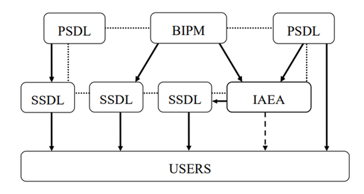
The traceability of user reference instruments to Primary Standards is therefore achieved either by direct calibration in a PSDL or, more commonly, in a SSDL with direct link to the BIPM, a PSDL or to the IAEA/WHO network of SSDLs. Most SSDLs from countries which are not members of the Metre Convention achieve the traceability of their standards through the IAEA. The arrows in the figure represent the calibrations which ensure the traceability chain to the international measurement standards and the dotted lines indicate comparisons of primary and secondary standards. The dashed arrow represents exceptional calibration of a user instrument by the IAEA in the event that a country has no SSDL and has very limited resources.
Ionization chamber calibration
Reference dosimetry for radiotherapy is carried out using an ionization chamber connected to an electrometer (dosimeter system). The dosimeter calibration in terms of absorbed dose to water, air kerma (for kV X-rays) or reference air kerma rate (for brachytherapy) must be traceable to a Primary Standard such as a free air chamber or a calorimeter, before it can be used clinically.
The use of a dosimeter having a calibration coefficient for Cobalt-60 gamma rays is a common characteristic of all dosimetry protocols and codes of practice for high energy photons and electrons, as well as for light-ion beams. These documents, introduced by national and international organizations, provide medical physicists with a systematic approach to the dosimetry of external radiotherapy beams. The IAEA TRS 398 and IAEA TRS 483 were developed for absorbed dose determination in external beam radiotherapy under ‘standard’ conditions and for small static fields, respectively.
In more recent years, absorbed dose standards operating at high energies have been used either directly for instrument calibrations or, more commonly, to determine values that correct the ionization chamber absorbed dose calibration coefficient for Cobalt-60 to higher energies. A few laboratories now offer dosimeter calibration service for megavoltage X-rays.
Calibrations are usually performed by substitution method in the PSDL or SSDL. Using this method, the absorbed dose to water/air kerma rate is determined at a point using a Primary or Secondary Standard. The ionization chamber to be calibrated is then placed at the same point as the reference standard and the response of the dosimeter is determined. The IAEA TRS 469 provides support to fulfil the need for a systematic and standardized approach to the calibration of reference dosimeters by the SSDLs.
The calibration of the dosimeter is only valid for the defined reference conditions and beam qualities. Any deviation from these conditions, such as the beam type, beam energy spectrum, depth in water, field size, temperature and pressure, humidity, ion recombination and polarity, must be considered in the clinic. Calibration and constancy checks of the dosimeters should be performed regularly, and a quality control system must ensure the dosimeters are working correctly and in a good state.
Dosimetry of external beam sources
Acceptance testing, commissioning and quality assurance of external beam equipment require many dosimetric measurements. A dosimetry protocol provides the formalism and the data to relate a calibration of an ionization chamber at a Standards Laboratory to the measurement of the absorbed dose to water under reference conditions in the clinical beam. Relative dose measurements, which use various types of detectors, provide further treatment beam characteristics needed for clinical use including data required to eventually operate a treatment planning system for the specific equipment.
Together with the local reference and field ionization chambers, additional equipment is needed for reference and relative dose measurements including an electrometer, thermometer, barometer, linear rulers, phantoms, beam scanning systems. Detectors different than ionization chambers (e.g., diodes, diamonds, films) may be used for relative dosimetry in specific cases.
Dosimetry of megavoltage standard radiotherapy photon beams
Dosimetry of MV radiotherapy beams typically involves Co-60 beams, or photon beams generated by clinical linear accelerators operating either in conventional mode with flattening filter (WFF) and nominal accelerating voltages in the range from a few MV to 25 MV, or in flattening filter free (FFF) mode with nominal accelerating voltage up to about 10 MV.
Water is recommended as the reference medium for measurements of absorbed dose. The phantom should extend to at least 5 cm beyond the maximum depth of measurements and all four sides of the largest field size employed at the depth of measurement. The ionization chamber should therefore be designed so that it can be put directly into water, or it must be used with a waterproof sleeve. The use of a sleeve may be a desirable option for positioning the chamber accurately at a given depth, although this depends on the equipment used for detector positioning.
Cylindrical or plane parallel ionization chambers are recommended for absorbed dose to water reference measurements in Co-60 beams, whereas only cylindrical chambers are recommended in linac beams.
The beam quality for high-energy photons produced by clinical accelerators is specified according to the IAEA TRS 398 Code of Practice by the tissue-phantom ratio, the TPR20,10. This is the ratio of the absorbed doses at depths of 20 cm and 10 cm in a water phantom, measured with a constant source-chamber distance of 100 cm and a field size of 10 cm x 10 cm at the plane of the chamber. Other beam quality specifiers, such as the percentage depth dose at 10 cm depth and the depth of the 80% depth-dose have been proposed by other organizations.
Special accelerator designs that cannot establish a conventional 10 cm x 10 cm field require specific dosimetry procedures which are discussed in section 5 of the IAEA TRS 483(Dosimetry of small and non-standard fields).
When performing relative dosimetry measurements, the stopping-power ratios and perturbation effects can be assumed (to a reasonable accuracy) to be independent of depth and field size. Relative ionization distributions measured with an ionization chamber can therefore be used as relative distributions of absorbed dose, at least for depths at and beyond the depth of dose maximum.
Dosimetry of high-energy electron beams
High energy electron beams used in the hospital usually range between 4 and 25 MeV. Water is recommended as the reference medium for absorbed dose measurements. Under certain circumstances and for beam energies below 10 MeV (R50 ≤ 4 g cm-2), a plastic phantom may be used; all depths must then be appropriately scaled.
The beam quality index for electron beams recommended by the IAEA and the AAPM is the half-value depth in water R50. This is the depth in water (in g cm-2) at which the absorbed dose is 50% of its value at the absorbed-dose maximum, measured with a constant source to surface distance (SSD) of 100 cm and a field size at the phantom surface of at least 10 cm x 10 cm for R50 ≤ 7 g cm-2 and at least 20 cm x 20 cm for R50 > 7 g cm-2.
When measuring the central-axis depth dose distribution with an ionization chamber, the measured depth-ionization distribution must be converted to the depth-dose distribution. For a beam of quality R50, this is achieved by multiplying the ionization current or charge at each measurement depth by the stopping-power ratio at that depth. Values of stopping-power ratios can be found in literature, for instance in the IAEA TRS-398.
Dosimetry of superficial and orthovoltage X-ray radiotherapy beams
Radiotherapy with low- and medium-energy kV X-rays is performed with superficial X-ray machines with a generating potential up to 100 kV or orthovoltage X-ray machines with a generating potential over 70 kV. The boundary between the two ranges is not strict and has an overlap between 70 kV and 100 kV. Clinically, the dose for superficial X-ray beams is often prescribed at the skin surface, while for treatments with orthovoltage X-ray beams, a point at the centre of the target volume is chosen, which is generally located at depths ranging from a few mm to a few cm. Dose determinations are therefore performed either in air in combination with backscatter factors, or in a phantom using appropriate depth dose data. Relative dose distributions are generally based on tables published in the literature or on isodose curves provided by the manufacturer of X-ray machines. Useful data for the calculation of dosimetric quantities for the dosimetry of low- and medium-energy kV X-rays can be obtained through the use of the GUI web app at http://52.233.195.208.
Depending on the beam quality, specified in terms of half-value layer (HVL) expressed in thickness (in mm) of aluminium or copper for superficial or orthovoltage X-ray beams, respectively, different types of ionization chambers should be used, as recommended in the IAEA TRS-398 Code of Practice. Ionization chambers of the plane-parallel type must have a thin entrance window and may need to have an additional plastic foil placed over the window when used in beams above 50 kV. The user determines the HVL of the beam and then chooses the calibration coefficient for that particular chamber by applying the calibration curve supplied by the standards laboratory. Output factors must be determined for all X-ray tube voltages and applicators using either the in-air or the in-phantom measurement method. Central axis depth dose curves are difficult to be measured in low energy beams and depth-dependent correction factors may be required. If a suitable detector for relative dosimetry cannot be identified in the clinic, published data may be used.
Dosimetry of proton therapy beams
According to the IAEA TRS-398 Code of Practice, reference dosimetry of broad-beam and pencil beam scanning (PBS) proton therapy delivery systems is based upon a calibration coefficient in terms of absorbed dose to water ND,w,Qo for a dosimeter in a reference beam of quality Qo. However, reference dosimetry conditions and procedures are substantially different between broad-beam and PBSdue to the intrinsic physical differences in the generated beams.
Methods for the calibration of beam monitors are well established for broad-beams. They are traditionally based on the determination of absorbed dose per monitor unit (MU), where one MU is correlated to a certain charge (or count number) generated in the beam monitor ionization chamber. Different methods are however required with PBS, where the number of protons per spot for each pencil beam has to be specified and controlled by the beam monitor.
Chapter 10 of the Second Edition of the IAEA TRS-398 provides updated recommendations for reference and relative dosimetry of proton beams. To support practical implementation of the updated TRS-398, the IAEA prepared a supplement to the chapter for proton beams. This publication will address methods to calibrate beam monitor chambers for pencil beam scanning delivery in terms of proton number per spot.
To request access to the supplement mentioned above, please fill in this document and follow the instructions provided in it.
Dosimetry of small and non-standard fields
The use of small fields in radiotherapy techniques has increased substantially, in particular in stereotactic treatments and large uniform or non-uniform fields that are composed of small fields such as for IMRT. This has been facilitated by the increased availability of standard and add-on multileaf collimators (MLCs) and a variety of non-conventional new treatment units.
Several dosimetry incidents have been reported due to the misunderstanding of small field dosimetry. For example, in 2007, an inappropriate detector was used to commission the 6 mm × 6 mm photon field defined by a microMLC leading to incorrect data being entered into the treatment planning system and to the mistreatment of 145 patients within a period of one year. The mistake was discovered by the manufacturer through a corroboration of the data measured worldwide by its users.
Small photon fields differ from conventional broad reference fields in their lateral dimensions causing the penumbrae at both sides of the field to overlap and most used detectors to be large relative to the field size. At least one of the following three physical conditionswill be fulfilledto determine if an external photon beam is small: (i) There is a loss of lateral charged particle equilibrium on the beam axis, (ii) there is partial occlusion of the primary photon source by the collimating devices on the beam axis, and (iii) the size of the detector is similar or larger compared to the beam dimensions.
The problem of small field dosimetry was addressed by presenting a formalism for the dosimetry of small and composite fields. The concept of two new intermediate calibration fields was introduced: (i) a static machine-specific reference (msr) field for those modalities that cannot establish conventional reference conditions and (ii) a plan-class specific reference (pcsr) field serving as an intermediate calibration field between the msr and the patient-specific clinical fields, thereby facilitating standardization of composite field dosimetry. The general formalism for reference and relative dosimetry of small static fields is presented in the IAEA TRS-483 Code of Practice. Guidelines for its practical implementation using suitable detectors and methods are provided for specific machines that provide small fields.
No ideal detector exists for small field dosimetry, so it is recommended to use two or three different types of detectors suitable for a particular measurement to improve assurance against unacceptable dose errors by means of redundancy in the results. It shall be noted that dosimetry errors are larger in small fields than in conventional beams mostly due to two reasons: (i) The reference conditions recommended by conventional Codes of Practice cannot be realised in some machines, and (ii) the measurement procedures for absorbed dose determination in small and composite fields is not standardized.
Dosimetry in brachytherapy
Dosimetry in brachytherapy involves knowledge of the strength of the source (reference air kerma rate or air kerma strength), and calculation of dose to tissue in proximity to the source when it is placed in the treatment position.
For hospitals, it is recommended that the source strength of all brachytherapy sources is measured on receipt with a well-type re-entrant ionization chamber and compared with the manufacturer’s certificate of source strength. Calibration of the hospital’s well-type chamber in terms of air-kerma rate is performed by an SSDL or PSDL for the specific radioisotope used.
Dose calculation formalisms have been developed for brachytherapy such as the AAPM TG 43 report. In this report, quantities are defined and discussed to calculate the absorbed dose rate to water surrounding the source. These quantitues include the air kerma strength and dose rate constant in water as well as the geometry, radial dose, and anisotropy functions. The factors are tabulated and disseminated for various brachytherapy sources. It is noted that relative dosimetry in brachytherapy is complex as a result of the high dose gradients involved and the influence of source geometry on the dose distribution.
In vivo dosimetry
In vivo dosimetry is a direct method of measuring radiation doses to patients receiving a radiotherapy treatment. The purpose of in vivo dosimetry is to verify that the treatment is carried out as prescribed. Together with other treatment verification tools used in radiotherapy, in vivo dosimetry might constitute a part of the quality management system in radiotherapy. It is a suitable method both to monitor treatment delivery and to detect errors early in the course of treatment. It may help to limit the escalation of an error to subsequent treatment sessions for a particular patient and to avoid systematic errors affecting many patients. Even if no errors are detected, the in vivo measurement provides a treatment record confirming that the dose was delivered correctly within the expected tolerance.
The simplest form of in vivo dosimetry for dose verification is to carry out an entrance dose measurement. It is easier to implement it in sites with regular body contours such as the pelvis and for simple techniques, which are not involving high dose gradients. For this reason, it is recommended that implementation begins with such sites and techniques. Once the system has been established and validated for these sites, more complex areas should be considered.
It is also possible to carry out exit dose measurements and dose measurements in organs at risk or natural body cavities such as the rectum and the oesophagus. One of the problems of the latter ones is that it may be very difficult to ensure that the dosimeter is correctly positioned at the point of interest and not moving. It is helpful if radiographic evidence of the position of the dosimeter can be obtained. Even when the position is accurately known, it may nevertheless be the case that the dosimeter is in an area of high dose gradients (such as rectum measurements during brachytherapy treatments), and practically useful action levels may be hard to achieve such that only serious misadministration can be detected.
In vivo dosimetry systems can be divided into two main operational modes: ‘Active’ dosimeters provide a direct display of the accumulated dose whereas ‘passive’ dosimeters do not provide direct readouts and need to be analysed after their exposition. Typical detectors used for in vivo dosimetry are TLDs (passive), diodes (active), MOSFETs (active or passive), OSLDs (passive) and films (passive). Electronic Portal Imaging Devices (EPIDs) (active) have also demonstrated to be used for in vivo dosimetry, or ‘transit dosimetry’, purposes.